Senior Design Project: IoT Device Control System
GitHub Repo Here
Dylan on LinkedIn
Welcome to an article detailing our Senior Project. My partner, Dylan St Laurent, and I embarked on the creation of a system called the IoT Device Control System. This project integrates a wide array of technologies and concepts, ranging from custom hardware design to thoughtful software implementation.
In this post, we will provide a comprehensive overview of all of our work, talking about the challenges that we face along the way and what solutions we provided. Additionally, we will get to see some of our demonstrations alongside a potential bonus demonstration. From ESP32 microcontrollers to React Native, our project touched on various aspects of modern IoT development. We hope you enjoy.
The Big Picture
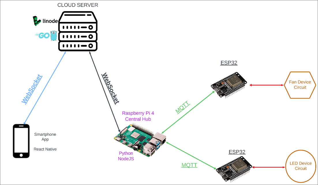
Before we get started, we present the Big Picture of our system. This way you can see how everything in the end plays together nicely. We will touch on every aspect in this blog post.
Cost
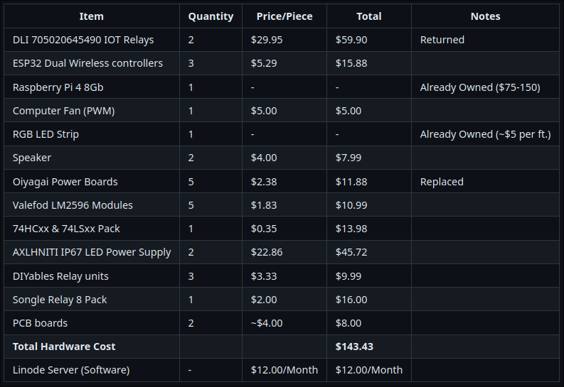
Overall, this project didn’t cost as much to accomplish; around $150 in software and hardware costs. This can be attributed to the various components needed to both wire and configure the wiring for the devices themselves. Things from speaker to power boards to 12 volt power supplies.
The only software cost that we thought we incurred was the price of a server, and this can range depending on what provider, but we decided to use Linode, and a server of a decent tier was around $12 a month, as pictured below. Things like the Raspberry Pi and the RGB strip were things we already owned, we didn’t factor that into the complete cost, although if you were to go ahead and fetch these on your own, prices may vary.
Hardware
This system uses a multitude of hardware devices to accomplish the specified goals set forth in the introduction. As mentioned earlier, the demonstrators have to effectively simulate small control systems for the consumer devices we aim to replicate: a fan and LED. These devices were chosen due to their commonality in homes across the US, ease of replication, and visual stimulus.
Device Wiring and Configuration
- The central microcontroller, an ESP 32S Development Board, was to be placed on the edge of our mounting platform to allow for access to the USB port for ease of access and potential compatibility with a hard cover.
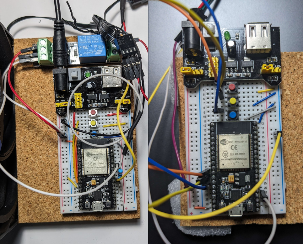
- In the initial design phase, devices were mounted to 11.5cm by 10cm wood platforms connected on 5.4cm by 8.1cm breadboards.
- The configuration of the breadboard layout varied by device due to the lack of requirement for a relay to be utilized on the LED device. The layout of these devices can be seen below.
To split the devices into various segmented circuits, the other main areas to be discussed are the power conversion circuits, audio response circuits, and user hardware input circuit.
Power Conversion Circuit
The most fundamental of these main circuits is the step down power conversion circuit. The device initially utilized for this area was an Oiyagai Power Board. This device was sufficient to power the ESP and some secondary devices, but struggled to supply enough current to the LED strip utilized in the demonstrator. This was promptly corrected by the utilization of Valeford LM2596 power modules with 3A maximum output current. Not featured on-board but a part of this circuit group, Axlhniti inverters were used to convert 120V wall power to 12V 5A to be utilized by the Valeford boards. In the final prototype phase, input is taken from the inverters using a DC barrel jack that traces to the Valeford boards on the PCBs.
Specific to the Fan Device, a Songole relay is fitted to the board to allow for control of device power access. This allows for the fan to be shut off from the circuit without having to set the RPM to 0. This provides a failsafe method to ensure that the fan is actually off. This allows for a true off state where no current travels to the fan.
Audio Response Circuit
Another of the main circuits utilized on the devices to supply another stimulus is the audio circuit. This circuit consists of a speaker connected to an onboard MAX98357A audio driver. This driver connects to the ESP 32 through 2 unspecific GPIO ports as well as the I2C SCL port. The other connections in this circuit include the Vin connection to the LM2596 as well as GND and Gain which is also sent to ground for a standard volume setting.
Hardware Control Input & Debouncing Circuit
The final main circuit group consists of two breadboard compatible buttons that are connected to power through separate 15kΩ resistors. The node that is connected to the button for power is also sent to the input of the LS74HC14 Schmitt-Trigger hex inverter with a 1kΩ resistor as well as a 1μF capacitor. This allows for a smooth transition between high and low which is detected by the Schmitt and then outputted on the opposing edge. This changes the buttons from their initial positive edge functionality that occurs on-pressed into an on-released logic. The output of the 74HC14 is sent to GPIO ports 25 & 26.
Printed Circuit Board
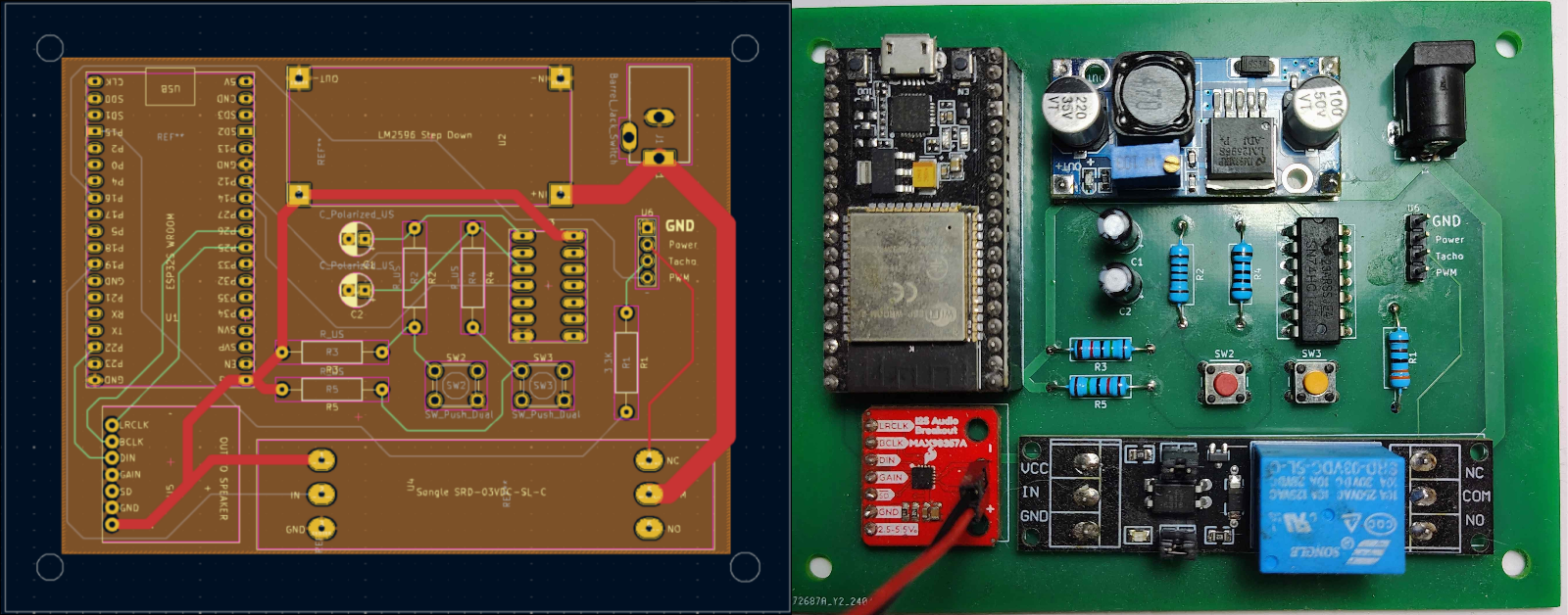
Above is the multi-layer schematic view of the Fan Device. For the purposes of this endeavor, a 4 layer PCB was decided on to allow for segmented circuits as well as proper trace shielding from cross-talk.
Upper Copper Layer (Open Air)
To begin, the uppermost copper layer was selected as the power layer. By placing the power traces in an open air layer it minimizes trace size due to heat distribution in open air. Referring to the supplied trace width calculator in KiCad, by placing the traces in open air trace sizes were reduced from 7.19mm minimum width to a 2.76mm width. This allowed for us to utilize 3mm traces for power providing overhead in case of unexpected operating systems while still drastically reducing size. Furthermore, devices were placed with minimum trace length in mind. By ensuring as many power traces were placed in the vicinity of each other as possible the separate lines necessary to send power were cut down to 2-3 main traces with branches leading to separate devices.
Second Copper Layer (Inner)
The second layer of the PCB is reserved for devices that have very little crossover traces with other layers. This is device dependent as there are differences in devices mounted and therefore mounting locations on both boards. On the LED Device PCB, this takes shape with the debouncing button circuit as there are no crossover locations between other layers. In the Fan Device PCB this contains the connections of the debounce circuit to the Schmitt inverter as well as connections from the audio driver to ESP.
Third Copper Layer (Inner)
Both boards utilize a ground plane on the third copper layer. This has multiple reasons, first of which is to supply the most heat distribution possible across the device. This eliminates the thicker trace requirement due to it being an interior layer as it is essentially one giant trace. Secondly, by having a ground plane in the third layer rather than the bottom layer the design implements what is essentially a shield between the bottom and upper layers, preventing cross-talk and noise between different traces.
Bottom Copper Layer (Open Air)
The bottom layer utilizes the setup from the third layer to allow for long traces that span across the board. On this layer we have placed any traces that could not be prevented from crossing over others to reach their respective locations. On the LED device this includes the audio driver connections to the ESP as well as signal to the LED. On the Fan Device this includes the outputs from the Schmitt Hex-Inverter, relay signal, and signal for the fan.
Software
Now comes my part of the story. Dylan took care of all the parts of the hardware, but it is important to realize that in an embedded context, there must be communication between both sides. So, you can say that development of each side was at a constant equal pace. Regardless, here is my side, the software side.
There are various points in the system that use the software to make things work. Beginning in the devices themselves, they must be programmed to perform the tasks that allow for end-to-end communication with the rest of the network. Other parts requiring software are the central hub, a server, and a client mobile app. Overall, these allow for an extensive inclusive system.
Device Programming
As mentioned by Dylan in the hardware section, the main hardware component for these devices was the ESP32. A simple way to start programming these devices is to use something more elementary and familiar, like you may know as the Arduino IDE and their libraries, which do provide support for these Espressif microcontrollers.
As always, there are pros and cons to each approach. For one, it is very quick to get something working and running using Arduino. For interacting with general purpose I/O ports, it can be just a few lines of code. However, once you start using simpler libraries, you realize that these environments abstract the control flow of a device’s operation, and it can get more difficult to acquire final control over what is actually happening.
So for this reason, and other reasons such as we wanted to get deep into a more industry-approved development framework, we pivoted over and decided to stick with ESPRESSIVE’s official ESP-IDF (IoT Development Framework)[5]. This, in the end, allowed us to program a device for greater control, and many protocols that we used were included in the libraries, so it was also very nice to see we had sort of hybrid complexity. The language we chose for writing the code was C, which once again allows for a more fine developer experience.
Real-time Task Management with FreeRTOS
One of the libraries included in the ESP-IDF repository is the FreeRTOS library[6]. To understand its place in the IoT development ecosystem and other firmware ecosystems for that matter, we must understand what an RTOS is.
As Shawn Hymel from Digi-Key described, “RTOS is an operating system, often a lightweight OS, that runs multi-threaded applications and can meet real-time deadlines”[7]. This means that we can leverage RTOS to ensure that we’re able to perform the necessary device functions in near real-time.
An implementation of the FreeRTOS library is using it for concurrent execution. Without an RTOS, we’re limited to executing only one part of the program with all of the microcontroller’s cores. This can prove to be inefficient for various parts of an IoT system, let alone for more industrial applications. We can approach our programming as multiple programs, let’s call them tasks, where each task can take care of a vital part of a device’s functionality.
Task Overview
Below is the list and description of each task in our devices, these provide a template for what a device should include to be apart of our system.
Wi-Fi Task
The Wi-Fi task is the initial thing that must be resolved, since without it, we have no remote control. One task for itself is enough to handle any complexities, such as abnormal connections.
MQTT Task
This protocol allows for a publish and subscribe architecture between a device and a central broker, where clients can subscribe to a specific topic and wait for events for which another client can publish on.# Implementing MQTT on Raspberry Pi for IoT Devices
Our implementation for this MQTT would be in the Raspberry Pi acting as the broker and the device is subscribing to topics to facilitate the parsing of received payloads.
Event Processor Task
This task is responsible for taking the commands from the MQTT task and performing the device-related function. For example, if in our LED device it receives a JSON payload in the color topic, then act accordingly and change the LED color to the RGB value of what the JSON payload was. Although we could have separated this into multiple tasks, this could potentially introduce race condition issues relating to IO and different controls.
Supplemental Tasks
These will range depending on what specific device is being programmed. For example, for every task, we have a heartbeat task, but for other tasks, we, for example, the fan where we want to count the RPM of our fan, we would have a counter task in the fan device, whereas the LED strip would not need that. These tasks can be easily implemented in a modular sense while keeping a general portion as a template for a new IoT device.
Below is a snippet of code that illustrates how we organized our tasks in each device, specifically this one being the fan. This is achieved by using external driver files and extensive refactors to provide as much clarity as possible.
#include "freertos/FreeRTOS.h"
#include "freertos/task.h"
#include "init.h"
#include "tasks.h"

#define BUFFER_SIZE 4096

void app_main(void) {
  init();
  vTaskDelay(1000 / portTICK_PERIOD_MS);
  xTaskCreate(wifiTask, "wifi", BUFFER_SIZE, NULL, 10, &wifiTaskHandle);
  vTaskDelay(5000 / portTICK_PERIOD_MS);
  xTaskCreate(mqttTask, "mqtt", BUFFER_SIZE, NULL, 10, &mqttTaskHandle);
  xTaskCreate(eventProcessor, "Event processor", BUFFER_SIZE, NULL, 10, &eventProcessorHandle);
  xTaskCreate(countTask, "countTask", BUFFER_SIZE, NULL, 8, &countTaskHandle);
  xTaskCreate(heartbeat, "Heartbeat", BUFFER_SIZE, NULL, 5, &heartbeatHandle);
  endInit();
}
Raspberry Pi Device Hub
To enable the MQTT function correctly, there must be a central place where this data is being exchanged, e.g., commands. This is where the Raspberry Pi comes in. It acts as a broker for the devices to connect and allows for that communication.
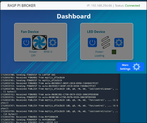
The Pi Hub also acts as a medium between the local network and the server, which will be discussed later. We use the Mosquitto library from Eclipse[9] to let us configure and run a broker on the Pi.
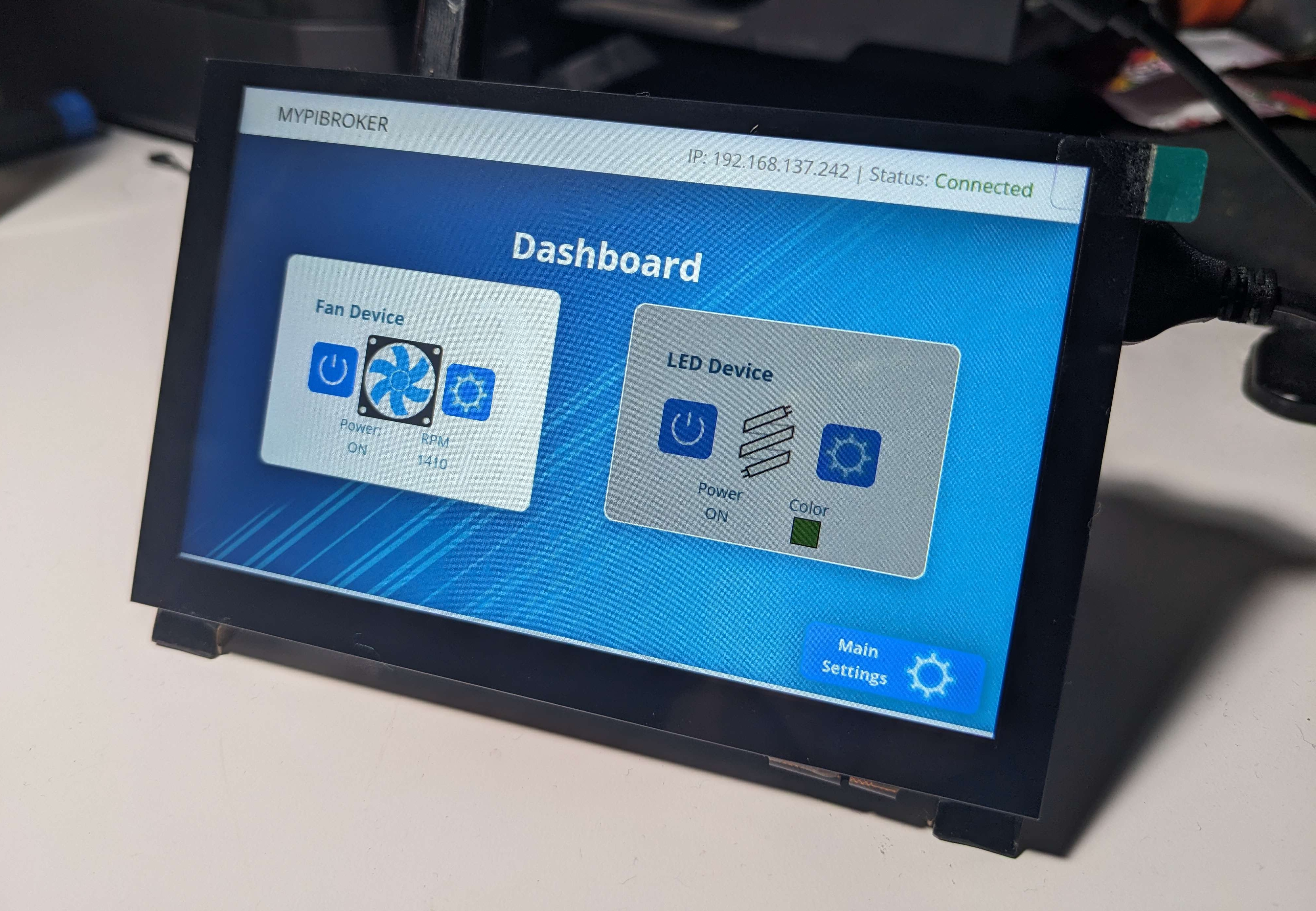
Another feature of the Raspberry Pi is the inclusion of a graphical user interface for additional control of the devices on-premise. In here, you will find all that is needed to power the devices, set their behavior, as well as having access to special modes for each device. This GUI app was made using the web app stack, HTML, CSS, and JavaScript. The backend, however, was unconventional and uses Python. The reason for this was because we wanted a way to incorporate a Chrome-based app with a backend that could connect directly to the MQTT broker.
After various research, we came across the Eel library[10]Eel is a backend Python library that we can use to serve web apps. And meaning we use Python, we can use MQTT libraries to integrate these both systems.
Server Architecture
Now we move on to what enables true remote control, the server. This server has capabilities to handle various clients that wish to control devices and transmits the status to them, back to them.
WebSockets
The protocol for data transmission with the client and the server we use was WebSockets. This protocol extends/upgrades from HTTP and presents as a bidirectional persistent connection. This ensures that connections are only dropped when there is an error or any peer of the client explicitly calls for a disconnection.
Golang
The language for running servers is very dependent on the use case. For example, we could have used something like Node.js or Bun for a backend. However, handling concurrent WebSocket connections could be more of a hassle in these frameworks. We ended up choosing Golang for its unique approach to concurrent execution, which would allow us to handle multiple clients and their command processing with ease. Golang’s concurrency model is similar to what we have mentioned with FreeRTOS that we use to program the ESPs. Each task in Go’s terms, goroutines, can run separately from a main thread or function. We ended up using this to allow us to broadcast and allow us to relay messages quickly.
Broadcast Function
The single most crucial function of the server is the broadcast function. As the name suggests, its main duty is to take data that is sent from a client and only send it to the broker, which then gets sent to the specified device for control. A common implementation for using WebSockets is a chatroom. When someone sends a message, it gets broadcasted to everyone else. In our case, it’s more controlled who gets messages. Below, you can see a code snippet of how we route messages depending on the agent that sends them.
func broadcast(messageType int, b[] byte, authWS * websocket.Conn) {
    if server.conns[authWS].Agent == "client" || server.conns[authWS].Agent == "commander" {
        for ws: = range server.conns {
            if server.conns[ws].Agent == "broker" {
                go func(ws * websocket.Conn) {
                    if err: = ws.WriteMessage(messageType, b);
                    err != nil {
                        fmt.Println("Write Error: ", err)
                    }
                }(ws)
            }
        }
    }
    if server.conns[authWS].Agent == "broker" {
        for ws: = range server.conns {
            if server.conns[ws].Agent == "client" {
                go func(ws * websocket.Conn) {
                    if err: = ws.WriteMessage(messageType, b);
                    err != nil {
                        fmt.Println("Write Error: ", err)
                    }
                }(ws)
            }
        }
    }
}
Mobile App
To complete this end-to-end communication, we have a client. In this case, it is represented as a mobile app. Apps are the de facto form of introducing new users and consumers to tech. All you have to do is download the app and follow whatever onboarding process there may be. We decided that a mobile app was the best route since it emulates the flow of control from other IoT control apps like Amazon Alexa and Google Home.
App Layout
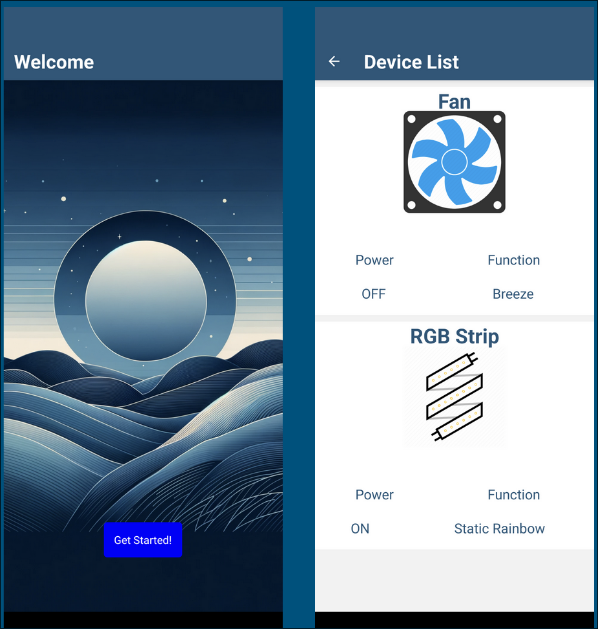
Here we show the app’s layout where there is a welcome page that then takes you to another page full of the devices and you get real-time stats regarding them. The welcome page can easily be adapted to, for example, a login system which would be an extension from this senior project.
React Native
Building apps has become filled with various options in terms of development. For Android-only apps, you can leverage Java with Android’s toolkits for app creation. For iOS, you would use something like Swift to bring your ideas to life. If you wanted to create an application for both platforms, then it would require you to learn both languages and frameworks.
Luckily, there exists React Native, a modern way to create cross-platform mobile apps from a single code base. We eventually decided to use this simply because it would allow us to deploy this application on both platforms with one code base, cutting on our development time to focus on other parts of our project. With the help of Expo[13], an extension to the React Native framework, the development process was straightforward and made testing and debugging much simpler.
On application startup, you connect to the WebSocket server running Go. This ensures that by the time the user enters the device list page, there are up-to-date stats. Inside each device, there is an interface that allows for control, as shown below. Upon each action, a WebSocket message is written to the server, and the broadcast function takes over and relays those messages.

Video Demos
After showcasing much of the project, below are various videos that were recorded in the process of creating this project. Things ranging from hardware tests to the Raspberry Pi GUI test to the mobile application test. Hopefully, you get a sense of what it was like working on this and what it took to complete the entirety of this project as we had envisioned.
The first set of videos is about testing the integration of the special modes via the Dashboard GUI, alongside the audio feedback feature.
There is a Frankensteined setup with 2 ESP’s; there was concepts for a third device but was discarded early on in the process. These videos showcase the viability of adding more modes.
This next video details the flow of the mobile app. On the monitor there are two terminal outputs: one being the Golang server and the other being the debug output of the mobile app.
One thing that was sort of a pain point when working on the mobile app was the amount of external components that needed to be installed for things like sliders and color pickers. I would have expected it to be more like HTML elements, but things are different here.
The last pair of videos are from Dylan’s progress regarding the button debouncing and the final PCB assembly.
Bonus Video: Voice Control
The videos aren’t over! Apart from the presentation during Symposium Day, linked here, you can check out a side quest that I decided to complete with another partner not related to Senior Project.
Below is a raw implementation of voice control of these devices using the OpenAI API to serve commands over the WebSocket server, alongside a framework for wake word detection and OpenAI’s Whisper model [20].
You can see my partner control the behavior of the Led Device, but it works just the same with the Fan Device.
Ending Remarks
Thank you for taking the time to read about our project. Documenting and sharing everything regarding this project serves as a meaningful end to this journey. Unlike typical academic projects with predefined paths, this endeavor allowed us to bring our own vision to life.
Throughout this post, I’ve aimed to illuminate various concepts that you might find applicable to your own projects. The dual purpose of this documentation is to not only record our process but also to inspire and equip others with knowledge they can carry forward into their own innovative pursuits. Sure, nothing we did here was innovative or ground-breaking; but more-so a learning experience that hopefully add to your arsenal of skills and understanding.
References
1 - Project Overview ↩
2 - Project Costs ↩
3 - Device Breadboard Configuration ↩
4 - PCB Schematic and Prototype ↩
5 - ESP-IDF (IoT Development Framework) ↩
6 - FreeRTOS library ↩
7 - “What is a Real-Time Operating System (RTOS)?” - Shawn Hymel ↩
8 - GUI MQTT Overview ↩
9 - Mosquitto MQTT ↩
10 - Eel library ↩
11 - Broker Setup ↩
12 - Mobile App Interface ↩
13 - Expo (React Native Extension) ↩
14 - App Control Interface ↩
15 - Initial testing of Audio Feedback ↩
16 - Breeze Mode activation via GUI, with proper audio feedback ↩
17 - Small Mobile App walk-through ↩
18 - Led Device Debounce Test ↩
19 - Fan Device Complete Assembly ↩
20 - Whisper Model (OpenAI) ↩
21 - Voice Control Demo ↩